 Vista
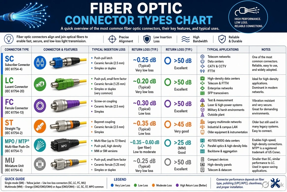
LC, SC, ST and FC describe common fibre-optic connector body styles and coupling mechanisms. UPC and APC describe connector end-face polishing, not cable types. LC usually uses a smaller 1.25 mm ferrule, whereas the traditional SC, ST and FC designs typically use 2.5 mm ferrules. Common single-mode UPC patch cords are blue and APC terminations are often green, but colour alone cannot prove compatibility. Do not mate UPC and APC ends against one another: the end-face geometries are different. Our three diagrams explain body identification, polish style and practical installation checks.
Updated 21 November 2026 · Visual learning only; comply with optical laser-safety and manufacturer specifications.
Fiber connector identification image gallery


Start with connector body, not cable colour
Fiber optical cables carry data as light through a glass core. A plug at the end aligns that core with a compatible mating interface, typically through a precisely fabricated ferrule. The connector has several separate characteristics: the housing style, the ferrule and polish, the fiber type, whether it is simplex or duplex, and the intended adapter or equipment port. These characteristics should be evaluated separately rather than reducing the choice to the colour of a cable jacket.
A fibre patch cord can be physically neat and still be unsuitable for a particular link. Single-mode versus multimode fiber, connector polish, optical transceiver wavelengths and the installation environment all affect link performance. Some optical components require vendor-defined connector types. Before ordering replacements, read equipment labels, existing part numbers and datasheets; take clear photographs of the connector face only after the link is confirmed safe to handle.
LC connector: compact latch, often selected for dense ports
LC connectors are widely used with modern transceivers, patch panels and higher-density cabling where compact form matters. They typically have a 1.25 mm ferrule, and a small latch mechanism resembles the push-release action familiar from some networking connectors. LC duplex assemblies are often joined as two small connectors, but simplex types also exist. Their small size does not mean LC works with every optical module.
When comparing LC to SC, the ferrule dimensions and body locking features differ. An LC plug will not normally fit an ordinary SC receptacle without appropriate mating equipment or a patch lead whose two ends are designed for different ports. It is common to encounter LC on a switch or transceiver side while another connector style appears at a wall or distribution termination. Check both ends and the cable fiber grade.
SC, ST and FC: identifying the larger legacy and current connectors
SC connectors typically have a rectangular push-pull body and a 2.5 mm ferrule. They are familiar in passive optical networks, distribution frames and equipment interfaces. ST connectors commonly use a round bayonet-style twist lock; older installations and test equipment may use them. FC connectors use a threaded coupling nut for a more secure mechanical connection in some specialist installations and measuring setups.
These descriptive shapes are useful for visual identification, but each family may have variants and specific mating requirements. A round metal connector in a photograph is not automatically FC; compare the actual thread, keying and ferrule interface. Different connector families are not intended to be directly pushed together without the correct adapter and verified polish/fiber configuration. The LC–SC–ST–FC figure helps narrow the basic family before reading a hardware specification.
UPC vs APC polish: what the labels actually describe
UPC stands for Ultra Physical Contact, and APC for Angled Physical Contact. In the commonly deployed APC interface, the ferrule end face is polished at an angle, often about eight degrees, so reflected light is better directed away from the optical path. A UPC end face has a different geometry. A simple picture can show why these polished surfaces are not designed to mate face-to-face with one another.
Single-mode UPC connectors are often colour-coded blue and APC connectors green in many product families; however, markings can vary by manufacturer and application. Colour is an aid, not a test result. Never place a blue UPC ferrule directly against a green APC ferrule in the wrong adapter, even if the bodies appear to fit. Such a mismatch can raise insertion loss or damage and contaminate end faces. Choose the finish required by the device and mated connector.
Single-mode versus multimode is a second independent decision
Single-mode optical fiber is typically used for longer transmission distances and particular transceiver technologies, while multimode fibre is used across many building and data-centre links. Labels such as OS2, OM3 and OM4 describe fiber classes, not simply the connector housing shape. LC and SC can both be found on different fibre types, so choosing ‘LC’ alone does not specify a cable that will perform correctly.
Jacket and boot colours are common visual shorthand, but do not infer fiber core type, connector finish or link suitability from appearance only. Read the cable printing and product code. Likewise, do not assume every green plug on a network rack means the same optical system. Check required wavelength, transceiver type, supported link budget and connector-end polish before making a replacement or modification.
Ferrule faces, adapter types and why cleaning matters
A fiber connector’s polished end face is small enough that dust, skin oil or a scratch can become a serious source of insertion loss. Corning recommends appropriate connector cleaning and checking before mating in many installation contexts. Use the correct fiber inspection and cleaning tools under approved procedures. Keep protective dust caps on unused connectors and ports, and do not touch the polished ferrule end with your fingers.
Never inspect an active fiber with a naked eye, ordinary microscope or improvised magnifier. Invisible optical energy may be present even when no visible light can be seen. Follow site laser-safety procedures and use suitable equipment to confirm a link is de-energised before inspection. Handling cut glass fibres also requires care because fragments can be difficult to see and can injure skin or eyes. Dispose of scraps using approved fibre-work methods.
How to use the three illustrated connector charts
The first diagram compares LC, SC, ST and FC connector bodies, including how their latch, bayonet or threaded coupling styles differ. The second graphic contrasts common UPC and APC terminations and warns against treating them as universally interchangeable. The third diagram illustrates the polished ferrule and why end-face geometry, surface condition and centering matter to an optical connection.
For purchasing or maintenance, write a specification in several parts: connector at side A, connector at side B, fiber grade, polish style on both ends, cable length and any special equipment requirement. A notation such as LC/UPC to SC/APC means the ends deliberately use different styles for different ports, not that you should mate UPC and APC together at one interface. Order using the equipment vendor’s optical requirements.
Fault-finding without damaging the optic link
If a fiber link is down, avoid repeatedly unplugging and remating random cords. Begin by checking the device alarms, port configuration and matching transceiver specifications. Verify that the patch-cord labels match the planned fiber type and end polish. A technician can use approved optical power measurement and cleaning procedures to investigate attenuation, dirty connectors or other faults. For professional installations, use inspection, cleaning and testing workflows suited to the link.
Do not conclude that a cable is safe just because an optical signal is invisible, nor that a green connector is safe to plug into every green port. Never mix connector polishes at a direct optical interface and never bend fiber more tightly than its product’s minimum bend radius. A small patch cord mistake can create intermittent failures that are much harder to diagnose than the initial mismatch.
LC vs SC vs ST vs FC quick comparison table
| Type | Common ferrule | Coupling clue |
|---|---|---|
| LC | 1.25 mm | Small latch |
| SC | 2.5 mm | Push-pull rectangular |
| ST | 2.5 mm | Twist bayonet |
| FC | 2.5 mm | Threaded coupling |
Frequently asked questions
What is the main difference between LC and SC?
LC is compact and commonly uses a 1.25 mm ferrule; SC is larger with a push-pull body and usually a 2.5 mm ferrule.
What do UPC and APC mean?
They refer to different ferrule end-face polish geometries used to control reflections and contact.
Can I connect UPC and APC directly?
No. Do not mate their differently polished end faces; use the correct matching connections.
Does green always mean APC?
Green is a common APC colour code, but part numbers and manufacturer specifications are the reliable check.
Can multimode and single-mode use an LC plug?
Yes, LC is a body style found in different fiber configurations. Confirm the fiber grade as well.
Is it safe to look into an unlit fiber connector?
No. Invisible laser radiation may be present; follow approved optical safety procedures.
Conclusion and sources
LC, SC, ST and FC describe common fibre-optic connector body styles and coupling mechanisms. UPC and APC describe connector end-face polishing, not cable types. LC usually uses a smaller 1.25 mm ferrule, whereas the traditional SC, ST and FC designs typically use 2.5 mm ferrules. Common single-mode UPC patch cords are blue and APC terminations are often green, but colour alone cannot prove compatibility. Do not mate UPC and APC ends against one another: the end-face geometries are different. Our three diagrams explain body identification, polish style and practical installation checks.
- Corning connector families and polish terminology
- Corning guidance for connector cleaning
- Corning optical-connector questions

























Share Your Opinion
Comments are closed on this post.