 Vista

A PCB connector can look almost identical to another part and still be incompatible. The fastest reliable identification method checks the connector’s actual manufacturer series, centre-to-centre pin pitch, number of positions, latch and key shape, wire terminal and mating part number. This visual guide compares familiar JST PH/XH-style wire-to-board plugs, Molex power families and ordinary pin headers, then explains how to identify a connector without guessing from a photograph. JST XH is nominally 2.5 mm pitch, whereas JST PH is 2.0 mm; a 2.54 mm generic header is not automatically a compatible XH mating connector.
Updated 21 November 2026. Identification guide; verify the exact series and electrical suitability in the manufacturer datasheet.
Four PCB connector identification pictures

PCB connector types: the five clues that matter more than appearance
When you see a loose wiring harness or a damaged connector on an electronic board, it is tempting to search for a ‘small white two-pin plug’. That description fits dozens of mechanically incompatible families. First count the positions, then look at the overall housing shape. Check whether the contacts are exposed male pins or female crimp terminals, the direction in which the plug enters the header, the presence of side wings, and the latch or friction ramp. Next measure pin pitch—the centre-to-centre distance between neighbouring contact positions.
Also note the cable exit direction, whether the plug is vertical or right-angle, PCB mounting style, lock strength, plating and operating environment. A part that barely slides into a socket may still have wrong contacts or a dangerously poor fit. Manufacturers distinguish housings, mating headers and crimp terminals by separate part numbers, so a complete repair order may require three different items rather than a single ‘connector’ product.
JST XH, PH, SH, GH and common confusion about pitch
JST is a manufacturer and a collection of named connector series, not a single universal socket. On its official product pages, JST identifies PH as a 2.0 mm-pitch wire-to-board family and XH as a 2.5 mm-pitch family. SH is commonly used for compact 1.0 mm-pitch connections, and GH for locking 1.25 mm-pitch connections; the particular mounting and locking details still depend on the catalogue model. Don’t identify a series from wire colour or the number of positions alone.
The frequent online phrase ‘JST 2.54’ can mix an XH-looking part with generic 0.1-inch/2.54 mm headers and clones. A 0.04 mm nominal difference sounds tiny, but mechanical mating is not defined by pitch alone. Many look-alike housings have incompatible terminal shapes or retaining features. A connector’s actual identity should be confirmed from a series drawing, not a retail nickname. Use the JST comparison figure to narrow choices, then check the maker’s mating table.
Molex connector families are not one interchangeable type
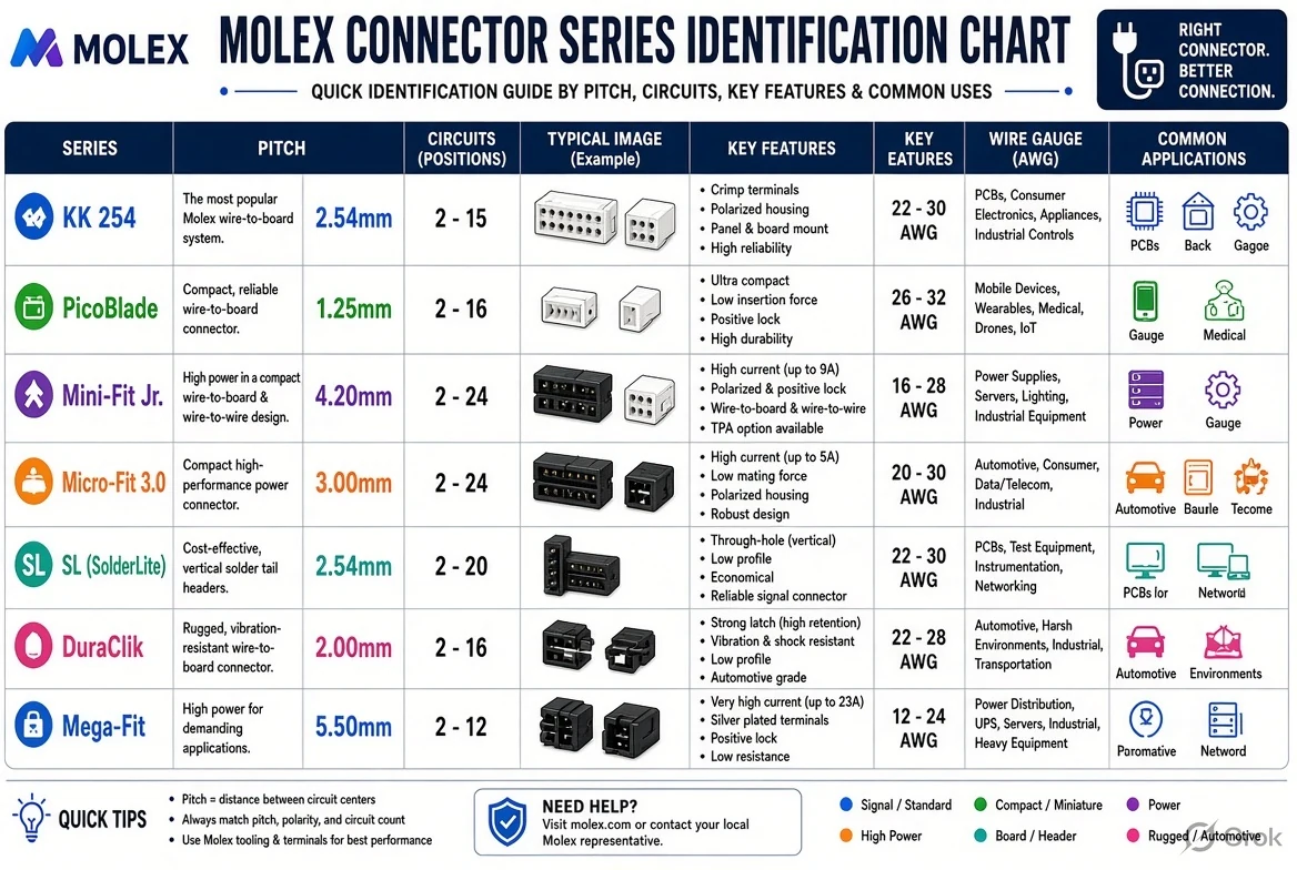
Molex is another connector manufacturer with many product families. Its Micro-Fit 3.0 range uses a 3.00 mm pitch in many relevant versions; Mini-Fit Jr. is the well-known 4.20 mm pitch family. These are not simply ‘large JST plugs’, nor are the two Molex families interchangeable. Their housings, terminals, latch geometry and electrical ratings belong to distinct systems. A connector photo can give clues, but the real test is the mating specification and part number.
People often say ‘Molex connector’ to mean an older computer power plug, a miniature PCB housing or any white plastic connector. That colloquial usage is not a technical specification. Check the complete manufacturer family name and the exact number of rows and contacts. Even within one family, variations in keying, polarization, mount direction, temperature and terminal gauge matter. Match the plug, crimp terminals and header as a documented set.
How to measure PCB header pin pitch correctly
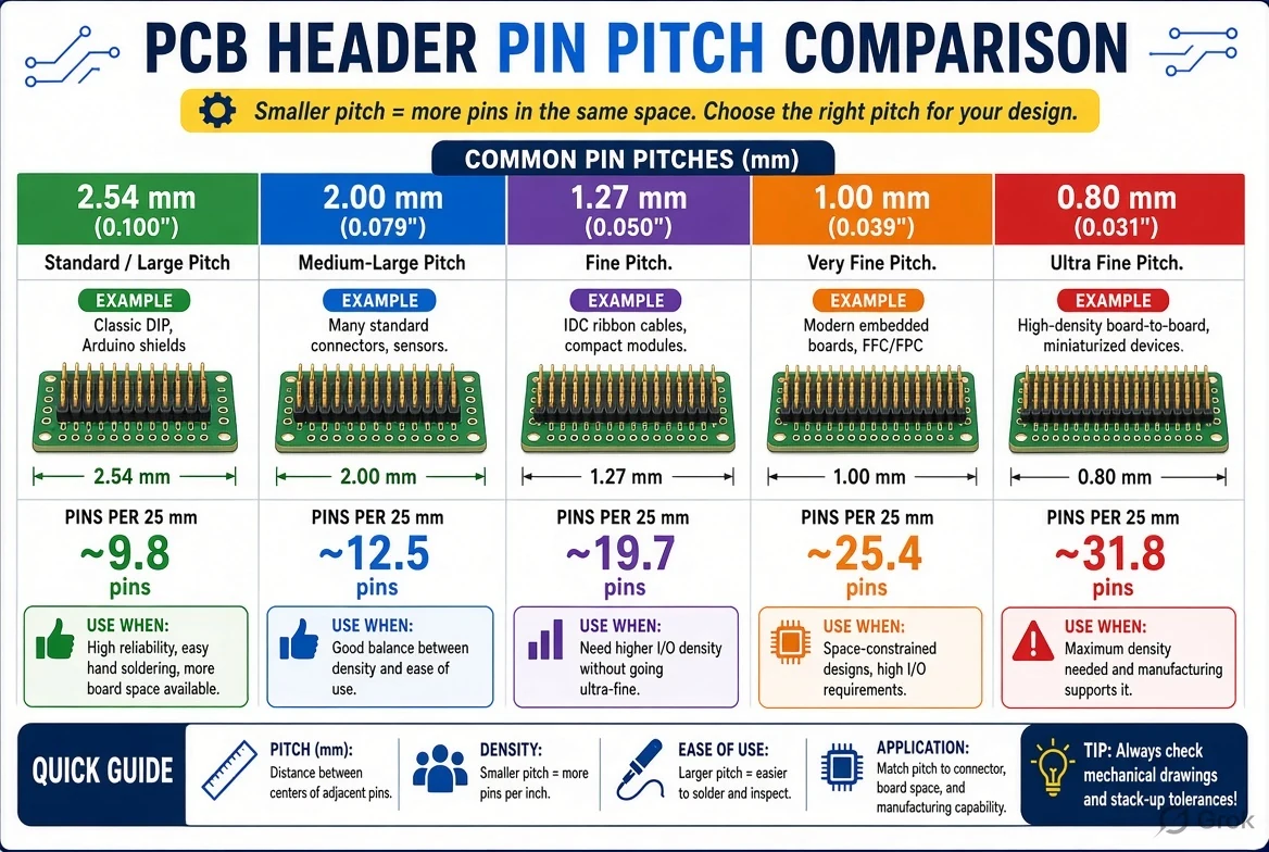
Pitch is the distance between adjacent pin centres, not the gap from one plastic wall to another. The easiest method on a multi-contact header is to measure the centre-to-centre span across several intervals and divide by the number of intervals. A row of five pins contains four intervals, not five. For instance, about 10 mm across four gaps suggests 2.5 mm pitch; around 10.16 mm suggests 2.54 mm. A caliper, magnification and the PCB footprint can help, but tolerances and measurement angle matter.
Avoid trying to measure a tiny connector while the circuit is live. Remove power and consider stored electrical energy before touching equipment. Measuring plastic body width or the full distance to the outside of the end pins commonly produces an incorrect pitch. The header-pin chart illustrates the principle; the official mechanical drawing controls final dimension and tolerance. Do not buy a replacement based on a single rounded phone-photo measurement.
Latch, friction lock and keyed plastic housing identification
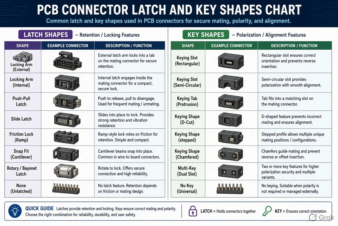
A friction ramp, positive latch, side-guided slot or keyed corner can tell you more than colour. Certain JST families depend primarily on friction retention while other types add more defined locking features. A keyed shroud can prevent reversed insertion, but only if the two halves belong to the designed mating system. Bent or cut-off plastic keys are signs of a potentially unsafe attempted substitution.
Inspect the housing with the unplugged connector under a light. Photograph the front mating face, side profile and upper latch separately; these views reveal the terminal openings and retention features. Note whether releasing the cable requires pressing a latch or gently pulling the housing. Never pull directly on thin wires to remove an unknown plug. If the retaining mechanism is unclear, consult the device service manual or connector documentation.
Wire gauge, current, voltage and crimp terminals
Correct fit is not enough for an electrical connection. Wire gauge, contact material, plating, terminal crimp and current-carrying ability must match the exact series and intended load. A wire-to-board connector intended for low-current signals should not be substituted for a power connection merely because the housing size resembles a higher-rated model. Ratings are dependent on the full connector configuration, conductor size, temperature and manufacturer test conditions.
Crimp terminals have matching tools and specified crimp heights or pull-force requirements. Squeezing a random contact with ordinary pliers can produce an intermittent or hot connection. For battery packs, mains-powered appliances and high-current equipment, use qualified repair procedures rather than informal visual identification. A poor contact can overheat long before its plastic housing visibly fails. The safest identification workflow leads to the complete part datasheet.
Read our four PCB connector charts in sequence
The first infographic compares JST connector family shapes. The next highlights Molex family differences. The third chart shows header pitch and the importance of counting centre-to-centre intervals. The fourth isolates latch and keyed-housing designs. These diagrams are intended for side-by-side visual study; they do not guarantee that any generic or third-party connector is an authorised mating part.
Start with a broad family shortlist, then take your exact measurements and find the corresponding manufacturer datasheet. Confirm the orientation and number of cavities, then compare mating part numbers, terminal part numbers, wire-gauge range and operating ratings. For ordering, write the series, pitch, pin count, row count and header orientation. A short product description such as ‘2 pin connector’ is almost never enough to avoid an incorrect purchase.
Troubleshooting an unknown connector: a repeatable checklist
Make a record of the circuit-board reference designator, device model and any connector markings. Disconnect safely, count pins, photograph three angles and measure the centre-to-centre pitch over more than one interval. Compare the actual housing geometry against official series drawings, then look up matched housings and contacts. If the part is burnt or melted, investigate why that happened rather than installing an identical connector into the same uncontrolled fault.
If uncertain, stop rather than forcing two nearly matching pieces together. A wrong connector may misalign contact positions, defeat polarization or reverse power and signal assignments. Connector compatibility is a mechanical and electrical statement together. No online image, including ours, can establish continuity, pinout or safe rated current from appearance alone. Follow manufacturer guidance and qualified repair practice for critical equipment.
Connector family quick comparison table
| Series | Common nominal pitch | Important caution |
|---|---|---|
| JST SH | 1.0 mm | Verify exact housing and crimp contacts |
| JST GH | 1.25 mm | Check keyed latch and mating drawings |
| JST PH | 2.0 mm | Not the same as XH |
| JST XH | 2.5 mm | Not automatically compatible with 2.54 mm headers |
| Molex Micro-Fit 3.0 | 3.0 mm | Family-specific mated pair |
| Molex Mini-Fit Jr. | 4.2 mm | Different keying and contacts from Micro-Fit |
Frequently asked questions
Is JST XH 2.54 mm pitch?
The official JST XH series is nominally 2.5 mm pitch; the very similar 2.54 mm label is often used loosely for generic headers.
What pitch is JST PH?
JST PH is a 2.0 mm-pitch connector family.
Are Molex Mini-Fit Jr and Micro-Fit the same?
No. Common Mini-Fit Jr versions use 4.2 mm pitch and Micro-Fit versions use 3.0 mm; their full specifications and mating parts differ.
Can I identify a connector by colour?
No. Colour is only a weak clue; check pitch, latch, cavity shape and maker series.
What is connector pitch?
The centre-to-centre spacing between neighbouring contacts.
Can I force a nearly fitting plug into the socket?
No. Use the specified mating series and pinout to avoid damage and electrical hazards.
Conclusion
The best PCB connector identification starts with measurable pitch, part-family drawings and a confirmed pinout—not a colour match. Reuse the visuals as a shortlist, then confirm the complete mated system.
Manufacturer references
- JST XH official connector series
- JST PH official connector series
- Molex power and signal cable families























Share Your Opinion
Comments are closed on this post.