 Vista
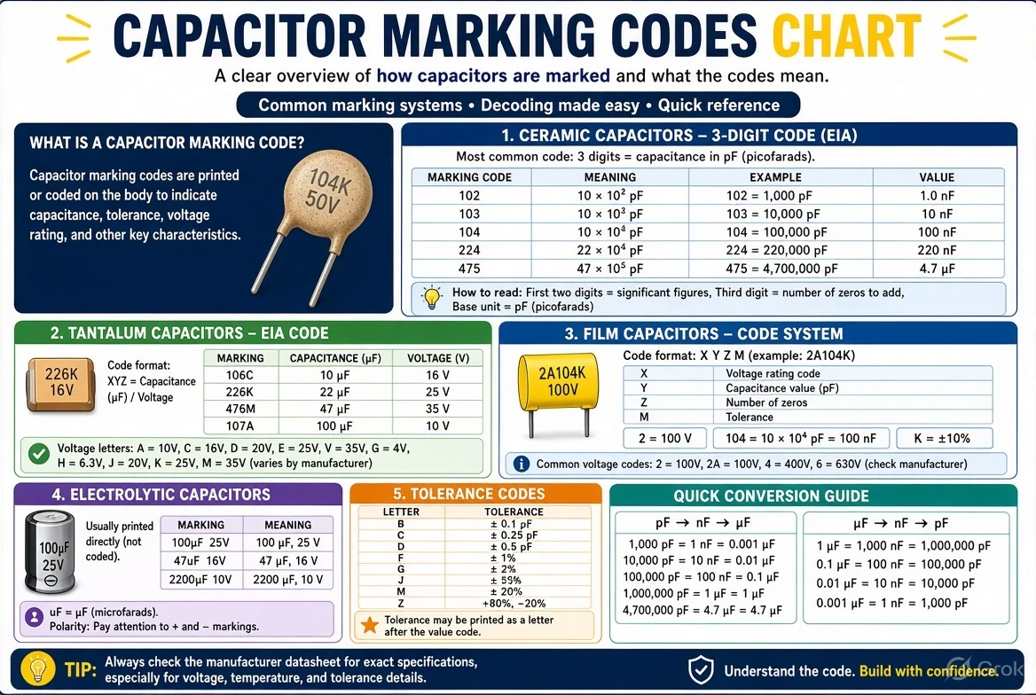
On many small ceramic or film capacitors, a three-digit code describes capacitance in picofarads: the first two digits are significant figures and the last digit is the power-of-ten multiplier. So 104 means 100,000 pF = 100 nF = 0.1 µF, while 103 means 10 nF and 472 means 4.7 nF. But a printed number alone does not establish voltage rating, tolerance, dielectric type or polarity. These four diagrams help read common markings and explain where additional manufacturer data is essential.
Updated 21 November 2026. Illustrations explain common component conventions, not electrical-safety certification.
Four capacitor marking and unit conversion charts

What does a capacitor code tell you?
A capacitor stores electrical charge and its nominal capacitance is measured in farads, commonly microfarads (µF), nanofarads (nF) or picofarads (pF). A small ceramic capacitor may print a compact numeric value rather than a long unit. The familiar three-digit system states a capacitance using picofarad as the starting unit. It is popular in component lists and on some larger leaded ceramics, although tiny surface-mount MLCCs may be unmarked.
The marking is not a full component datasheet. Two capacitors both described as 104 can differ in physical dimensions, rated voltage, dielectric such as C0G or X7R, tolerance, temperature response and intended application. This is especially important when selecting a substitute on a power-supply board. A plausible value is not enough to show that a replacement is electrically suitable.
Three-digit ceramic capacitor formula: decode 104 and 103
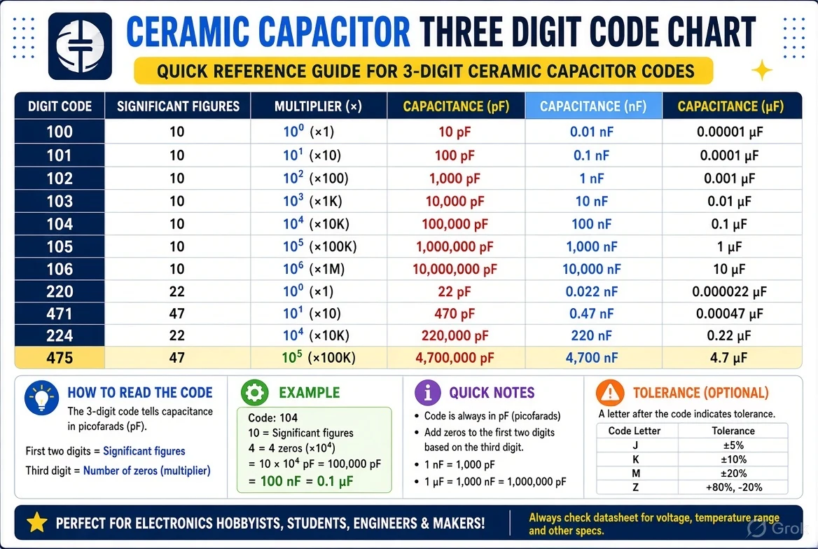
Take the first two numbers as significant digits and the third as the number of zeros, with the result in picofarads. Thus 104 = 10 × 10⁴ = 100,000 pF. Convert pF to nF by dividing by 1,000: that is 100 nF. Divide by another 1,000 for µF: 0.1 µF. Code 103 = 10 × 10³ = 10,000 pF = 10 nF = 0.01 µF.
Other useful examples are 102 = 1 nF, 223 = 22 nF, 472 = 4.7 nF and 105 = 1 µF. This explanation applies to the usual three-digit capacitance-marking convention. It should not be blindly applied to every marking on an electrolytic capacitor, connector or unidentified component. First check whether the part and context are consistent with a capacitor value.
pF, nF and µF conversion without mistakes
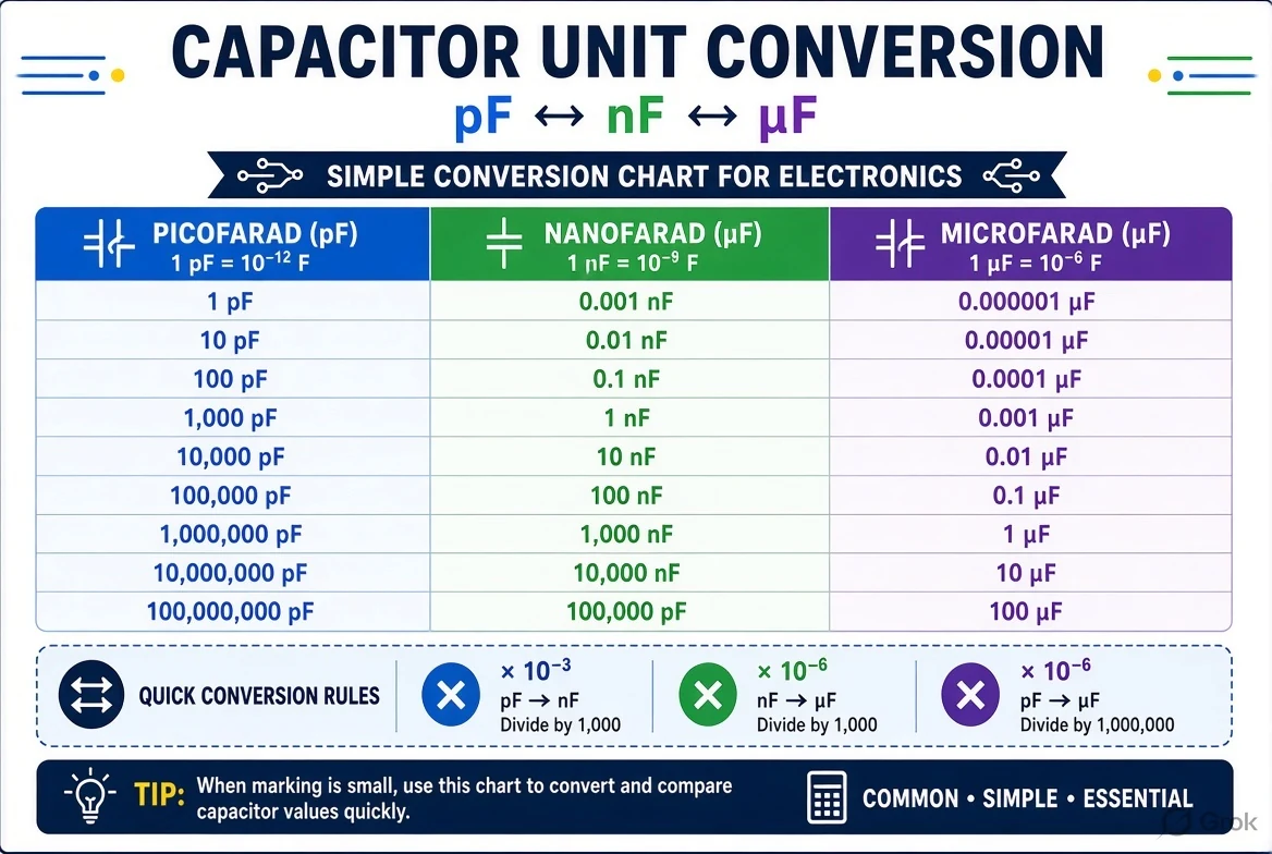
The key conversion facts are 1 nF = 1,000 pF, and 1 µF = 1,000 nF = 1,000,000 pF. Moving from pF to nF divides the number by 1,000. Moving from nF to µF divides it by another 1,000. This avoids the frequent confusion between 0.1 µF and 0.01 µF when reading 104 and 103. The unit chart below shows both quantities side by side.
In a repair notebook, write the code and full unit conversion before ordering a replacement. For example, 472 is 4,700 pF, or 4.7 nF, not 472 nF. Code 105 is 1 µF in this convention, not 105 µF. If a schematic says 100 nF while the spare pack says 0.1 µF, those are the same nominal capacitance. Voltage and dielectric specifications must still be checked independently.
Tolerance letters J, K and M: what they commonly mean
Component markings and order codes often use J for ±5%, K for ±10% and M for ±20% capacitance tolerance, but this depends on the component family and the part-number format. A marking such as 104K commonly denotes nominal 0.1 µF with a K tolerance designation in a conventional ceramic code. Do not use a generic table to override a specific manufacturer’s published marking guide.
Tolerance describes a manufacturing range under stated test conditions, not the full behaviour of the capacitor in every circuit. Some ceramic dielectrics change capacitance significantly with temperature and DC bias. For an MLCC in a precision or power circuit, the dielectric and bias characteristics can matter as much as the nominal tolerance. A measurement method can also affect the displayed reading.
Voltage markings: why 104 does not reveal the rating
A capacitance code such as 104 describes a nominal value only. It does not prove whether a part is rated 16 V, 25 V, 50 V, 100 V or something else. Manufacturers may use additional letter-number codes for voltage ratings, and their meanings depend on the series and order-code structure. Inspect the datasheet or original BOM rather than guessing from a random online chart.
Voltage class is particularly important for mains-connected capacitors and those across safety-critical isolation barriers. Approved X or Y safety capacitors must meet appropriate application requirements; a generic ceramic part with equal capacitance is not a drop-in replacement. Never alter mains or high-energy circuits on the basis of this infographic. Qualified service instructions and correct certified parts are essential.
Electrolytic and tantalum polarity markings
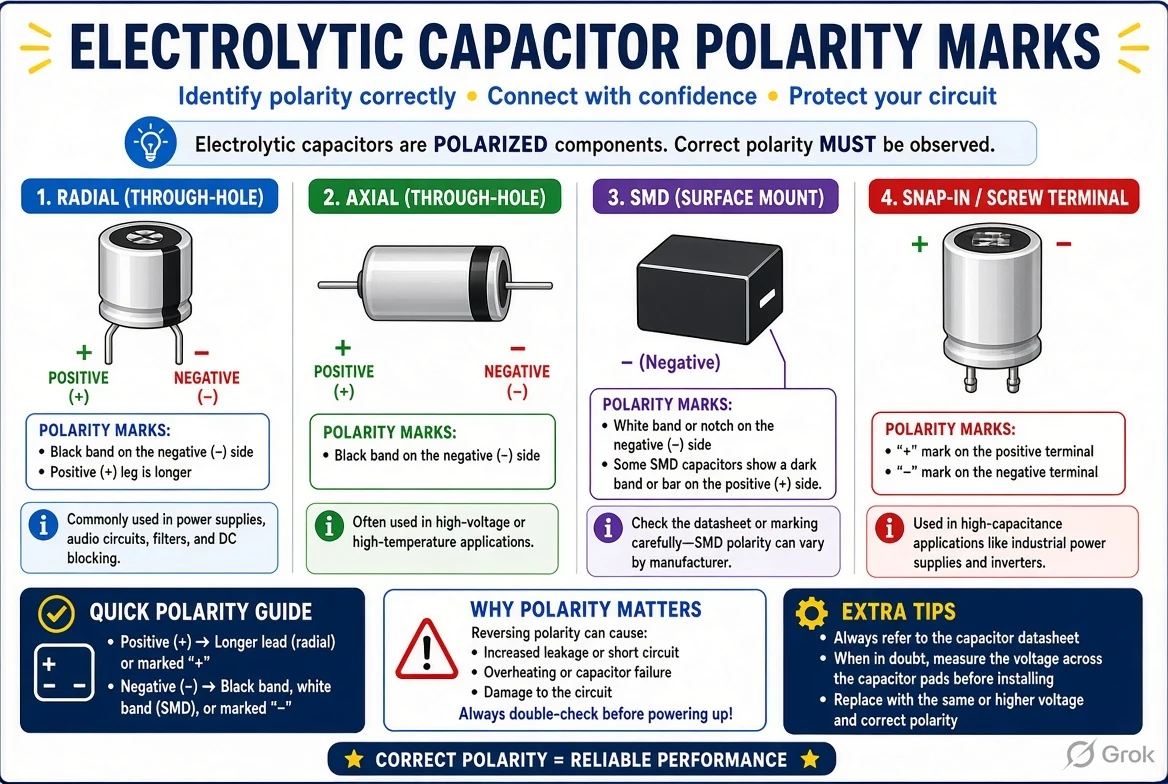
Many aluminium electrolytic capacitors are polarised. On familiar radial aluminium electrolytics, a printed stripe often identifies the negative terminal; some packages also use lead length and symbols. Tantalum capacitor markings can follow a different convention, commonly indicating the positive terminal, so copying the ‘stripe equals negative’ assumption across technologies is dangerous. Always inspect the exact part datasheet and circuit polarity.
A polarised capacitor connected backwards can fail and create a safety hazard. Before handling equipment, disconnect power and treat stored energy as hazardous. Larger capacitors can retain charge after the plug is removed. Do not short terminals with a screwdriver as a casual discharge method; high-voltage equipment should be serviced by competent personnel following a verified procedure. No chart can verify a capacitor is safe to touch.
How to read the four illustrated reference charts
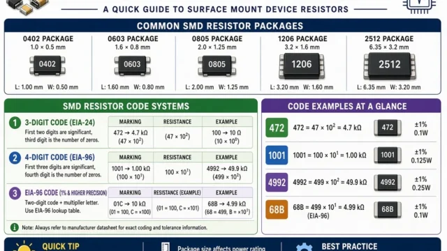
The first figure focuses on three-digit ceramic capacitor values, which is where 104, 103 and 472 searches lead. The second explains common electrolytic polarity cues and their limitations. The third highlights voltage and tolerance markings so the reader does not confuse capacitance with suitability. The fourth lays out the pF–nF–µF unit conversions that are necessary for comparing schematics and parts catalogues.
Use them in order when identifying a known component: confirm the component family, decode the nominal capacitance, convert units, check polarity if applicable and then cross-check voltage, dielectric, dimensions and operating temperature from manufacturer information. The first correct number on a chip is rarely the end of the selection process. For study problems, record each assumption explicitly.
Safe troubleshooting and common code-reading errors
Never test capacitance or resistance on a powered circuit. For any equipment with mains input, large batteries or charged capacitors, stop unless you have the required training and validated discharge procedure. For an isolated, verified-safe component, an appropriate capacitance meter may help, but in-circuit measurements can be distorted by parallel pathways. Some large-value ceramic capacitors test differently depending on applied bias and frequency.
Common mistakes include reading 104 as 104 µF, confusing resistor code 103 with capacitor code 103, swapping pF and nF, assuming all marked capacitors are nonpolar and treating a visual voltage code chart as a universal standard. A clear notebook with component type, value, voltage, dielectric, tolerance and source datasheet is much more dependable than a remembered single symbol.
Capacitor code, pF, nF and µF reference
| Code | pF | nF | µF |
|---|---|---|---|
| 101 | 100 pF | 0.1 nF | 0.0001 µF |
| 102 | 1,000 pF | 1 nF | 0.001 µF |
| 103 | 10,000 pF | 10 nF | 0.01 µF |
| 104 | 100,000 pF | 100 nF | 0.1 µF |
| 223 | 22,000 pF | 22 nF | 0.022 µF |
| 472 | 4,700 pF | 4.7 nF | 0.0047 µF |
| 105 | 1,000,000 pF | 1,000 nF | 1 µF |
Frequently asked questions
What is capacitor code 104?
100 nF, which equals 0.1 µF or 100,000 pF, in the common three-digit capacitance convention.
What does code 103 mean?
10 nF or 0.01 µF.
Is 472 a 4.7 nF capacitor?
Yes, in the typical three-digit pF-based system.
Can I determine voltage rating from 104?
No. Check part details and datasheet.
Is the stripe always negative?
No. Aluminium electrolytic and tantalum marking conventions can differ; confirm the exact type.
Conclusion and verified reference sources
On many small ceramic or film capacitors, a three-digit code describes capacitance in picofarads: the first two digits are significant figures and the last digit is the power-of-ten multiplier. So 104 means 100,000 pF = 100 nF = 0.1 µF, while 103 means 10 nF and 472 means 4.7 nF. But a printed number alone does not establish voltage rating, tolerance, dielectric type or polarity. These four diagrams help read common markings and explain where additional manufacturer data is essential.
TDK Electronics: manufacturer technical resources · KYOCERA AVX: 104 capacitance component example · TDK capacitor measurement notes.
























Share Your Opinion
Comments are closed on this post.