 Vista

Need an electric circuit school project with labelled diagrams? This guide includes four educational pictures: a Simple Circuit Working Model, its schematic, a Series versus Parallel comparison and a Logic Gates Truth Table. Students in roughly Classes 6–11 can progress from a battery-switch-load circuit to understanding separate branches and then simple digital decisions represented by zeros and ones. A circuit diagram is meaningful only if its connections and component ratings make sense. For physical demonstrations use teacher-approved, low-voltage kits and current limiting where needed, especially for LEDs. Never connect experimental paper circuits to mains electricity. The existing timed image-download experience is retained for each poster.
What is a complete electric circuit?
A simple electric circuit needs a suitable source of electrical energy, conductors forming a closed path and a load. A switch opens or closes the intended route, allowing current to change. Do not teach that the battery ‘contains current’ in the same way a tank holds water; it maintains a potential difference and supplies energy to the circuit. Joining battery terminals directly with wire creates a short circuit rather than useful work and can overheat cells or conductors. A proper resistance or rated load protects the system. Check all schematic connections rather than assuming that any picture showing a battery and lamp is correctly wired.
Picture 1: Simple Electric Circuit Working Model
The first poster introduces a battery, switch, light source and connecting leads. For an LED model, use the correct polarity and a suitable current-limiting component selected for the available supply. An ordinary filament bulb and an LED are not interchangeable at every voltage. Students can observe that closing a switch completes the intended path and opening it interrupts the current. Ensure no exposed wire bypasses the load. Younger pupils can use a preassembled low-voltage kit and a cardboard diagram rather than cutting and stripping conductors. Describe the actual behaviour seen; an incorrect LED connection may prevent illumination.

View / Download after 15-second wait
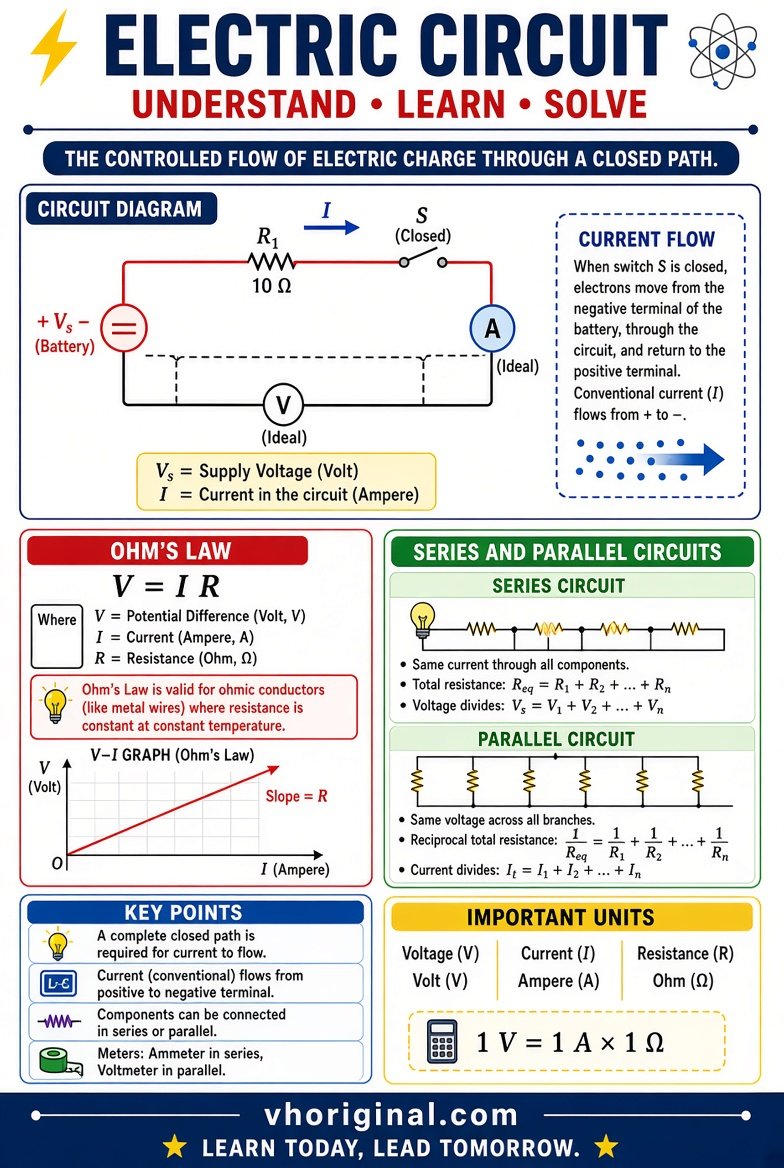
Picture 2: Labelled Circuit Schematic
The symbols for a cell or battery, switch, resistance and lamp help communicate a circuit without illustrating every piece of real wire. Conventional current direction is often shown leaving the positive terminal through the external circuit. The direction of electron flow through a metal is opposite, so identify which convention the arrow uses. A junction dot indicates conductors that connect; crossing lines without a junction need not be connected. One misplaced dot can change the entire circuit. Compare the generated diagram with a textbook before using it to guide wiring. A schematic explains a design but does not replace rated-component and electrical-safety checks.
View / Download after 15-second wait
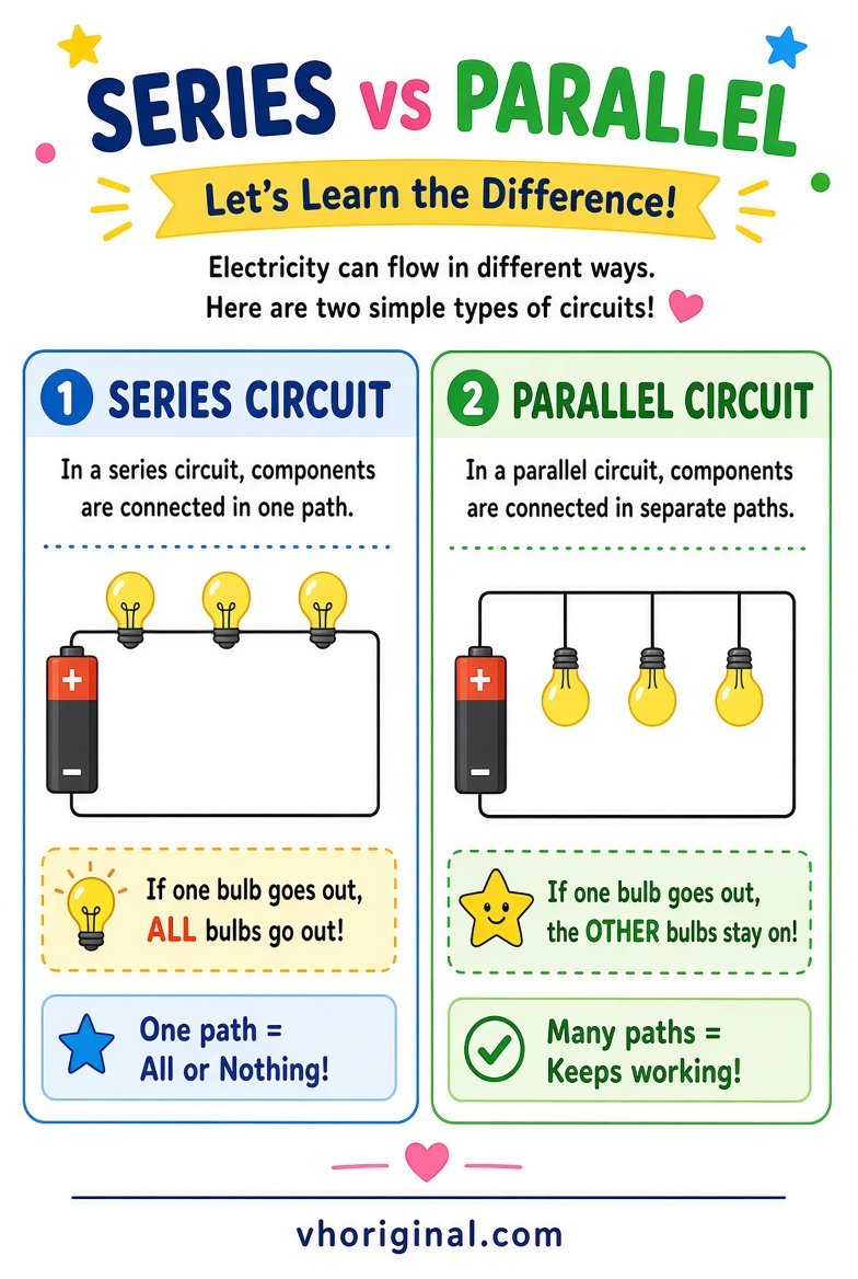
Picture 3: Series versus Parallel Circuits
In a series circuit, the same current passes through all components along a single path, while the total voltage is shared among components according to their properties. In a parallel circuit, each branch connects across the same pair of nodes, so each branch has the same potential difference. Currents can differ by branch and add to the source current. Brightness comparisons depend on battery condition, lamp ratings and circuit resistance; do not promise that every parallel bulb is always equally bright in every setup. A broken series path interrupts all loads, while another functioning parallel branch may continue working independently.
View / Download after 15-second wait
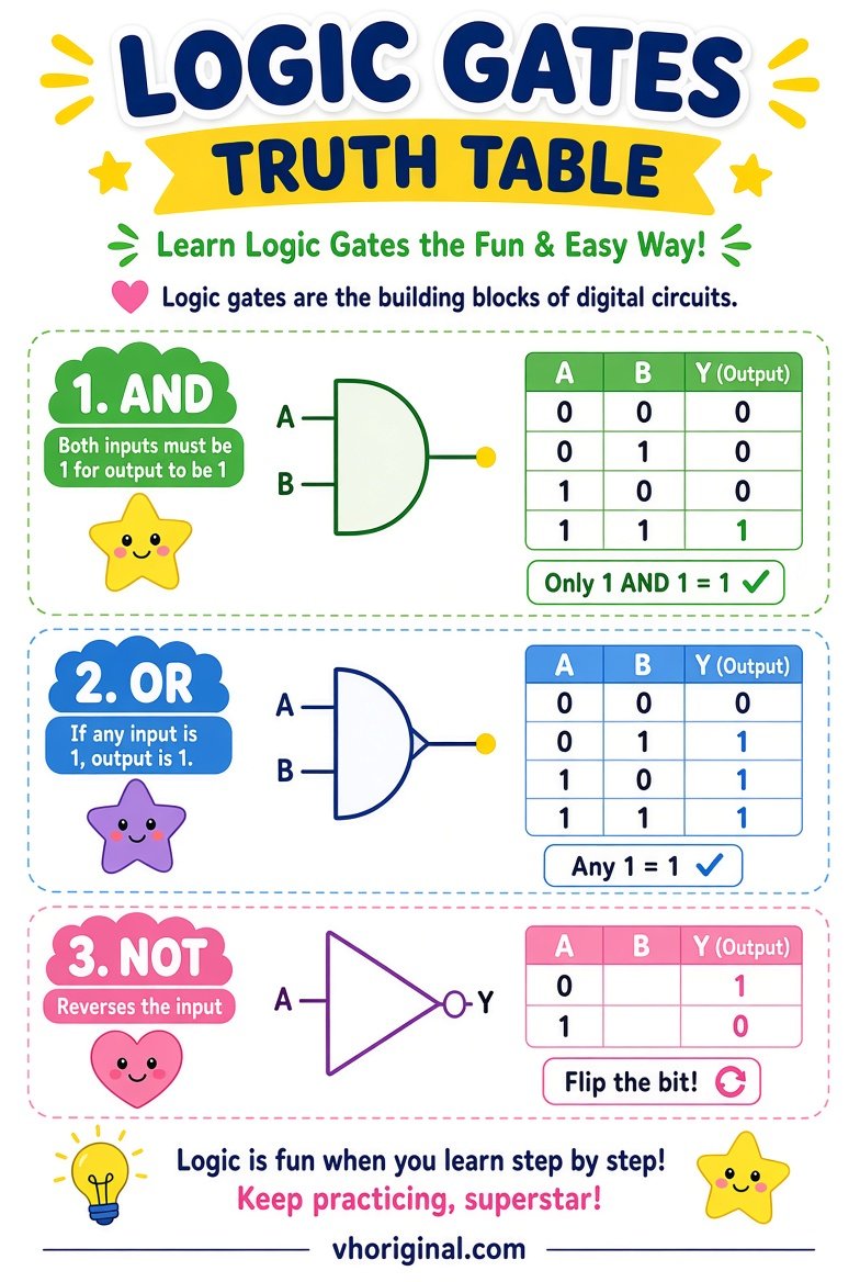
Picture 4: Logic Gate Truth Tables
Digital logic gates operate on logical values, commonly written 0 and 1. A two-input AND gate outputs 1 only when both inputs are 1. OR outputs 1 if either or both inputs are 1. XOR outputs 1 when exactly one input is 1, so its output for inputs 1 and 1 is 0. A NOT gate has one input and reverses its logical state. These definitions should match every row of a truth table. Logic values are not directions to connect arbitrary voltages; real chips require rated supplies and proper connections. A hand-drawn truth table is an effective school activity without any powered hardware.
View / Download after 15-second wait
Materials and a clear project layout
Use chart paper, pencils, ruler, colour pens, clean cardboard and optional teacher-approved low-voltage kits. Give each circuit a separate area or page so the lines and junctions remain readable. Younger students may focus on one battery, one switch and two loads arranged in different ways. Older students can add digital logic symbols and tables. A legend helps viewers tell switches from resistors and connected junctions from crossed wires. Do not place several wiring diagrams on top of each other in an attempt to fit every poster on one A4 sheet. Accuracy and readable labels matter more than decoration.
Step-by-step demonstration and observations
Begin with the power disconnected and draw the circuit you intend to assemble. Arrange two suitable loads in series, check ratings and have the teacher verify the connections before energising briefly. Note the actual light response or meter readings, then switch off and reconfigure the circuit into parallel branches. Never rewire while a source is powered. If measurement equipment is available, choose correct ranges and connect an ammeter in series and a voltmeter across a component. Do not deliberately short a battery or leave hot loads operating. Record differences that you really observe rather than invented numerical results.
Presentation, common mistakes and downloads
Explain how series components share current, parallel branches share voltage, and AND versus XOR outputs differ. Check LED polarity, junction dots and current limiting. Disconnect power before troubleshooting. All poster clicks use the existing 15-second advertising download route, not a direct-file shortcut. Verify symbols before copying them into a hand-drawn school assignment.
Frequently asked questions
What is the main series-circuit rule?
The same current passes through components in a single series path.
What is common across parallel branches?
Their voltage is the same when connected to the same two nodes.
When does AND output 1?
Only when both binary inputs are 1.
What is XOR for inputs 1 and 1?
0, because XOR is true only when the inputs differ.
Conclusion and sources
Correct diagrams, safe low-voltage observations and accurate truth tables let students connect basic electrical circuits to digital logic.
Related published projects: Wind Turbine LED · Robotics and LDR Model
References: OpenStax — Series Circuits; OpenStax — Parallel Circuits.
Explore more: 44 school project models, charts and pictures











Share Your Opinion
Comments are closed on this post.