 Vista
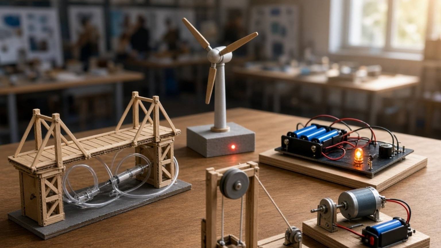
Need DC motor, AC generator and transformer working principle diagrams for a school project? This guide brings together three educational posters for roughly Classes 8–12. They involve electricity and magnetism but perform distinct tasks. A motor converts electrical energy into mechanical motion, a generator uses mechanical motion to produce electrical energy through induction, and a transformer transfers energy between circuits through changing magnetic flux. The posters can support a labelled chart, safe demonstration or science exhibition explanation. A critical safety boundary applies: never connect an improvised classroom transformer or exposed circuit to a household mains socket. Paper models and instructor-approved low-voltage kits are sufficient to teach the underlying physics.
How do a motor, generator and transformer differ?
A suitable DC motor develops torque when electrical current interacts with a magnetic field, allowing a shaft to rotate. A generator works in the other direction in the broad energy-conversion sense: mechanical input changes magnetic flux and can induce voltage. A transformer does not need a spinning shaft; changing current in one coil produces changing magnetic flux that links another coil. These devices should have separate Input, Working Principle and Output labels on a project board. None generates useful energy for free. Losses in resistance, friction and magnetic materials mean real efficiency is never simply an unconditional promise of one hundred percent.
Picture 1: Simple DC Motor Working Model
A classroom poster may show a coil, permanent magnets, rotor, shaft, brushes and commutator. In a traditional brushed DC motor, a commutator reverses suitable coil connections as it turns, supporting continued torque in one direction. Not all modern motors use brushes, so this image represents one common principle rather than every possible motor construction. A ready-made toy motor matched to a small, rated battery can demonstrate rotation safely. Do not run exposed wire coils until they become hot or attach a large unguarded blade. Keep fingers, hair and loose clothing away from rotating parts. Record the actual motor behaviour rather than invented speed data.

View / Download after 15-second wait
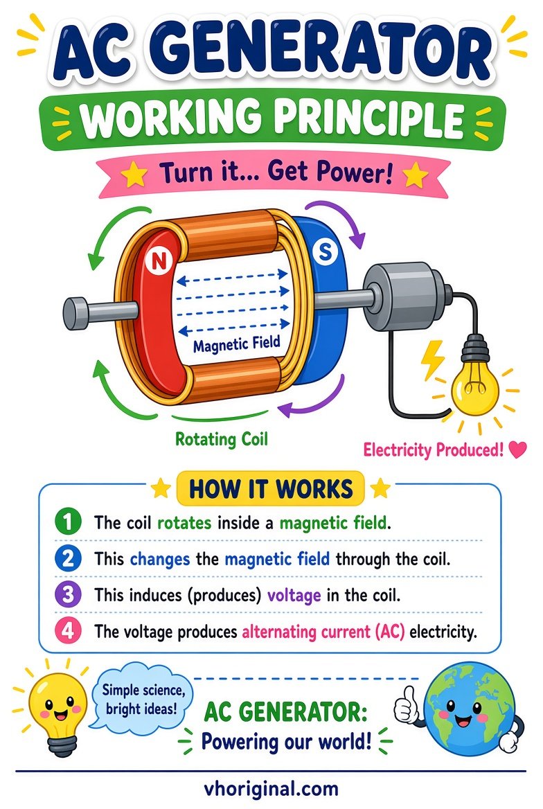
Picture 2: AC Generator Working Principle
Electromagnetic induction occurs when the magnetic flux linked with a circuit changes. In a simple alternating-current generator, a coil may rotate in a magnetic field, resulting in a time-varying induced voltage. Educational illustrations often include slip rings and brushes to connect the rotating coil to an external circuit. The output depends on speed, field strength, coil properties and connected load. A hand-cranked classroom generator may require a particular speed to produce a visible electrical effect. Do not connect an unknown AC output directly to a bare LED or use a mains alternator for the experiment. Draw separate arrows for mechanical input and electrical output.
View / Download after 15-second wait
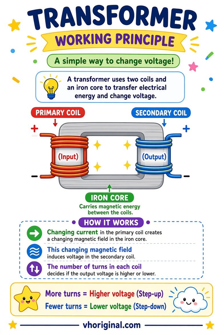
Picture 3: Transformer Working Principle
A simple transformer has a primary winding, secondary winding and a magnetic path such as a suitable core. A changing current in the primary produces a changing magnetic flux, which induces voltage in the secondary. In an ideal transformer, the voltage ratio relates to the ratio of winding turns. More secondary turns can increase the voltage, but this does not increase available energy without limit; current and losses matter. A conventional transformer does not continuously transform a steady DC supply, because a sustained changing flux is required. Avoid dangerous misconceptions such as connecting an unknown transformer directly to 230-volt mains to see if the model works.
View / Download after 15-second wait
Induction and the direction of energy transfer
Faraday’s law connects induced electromotive force to the rate of change of magnetic flux. It helps explain both generators and transformers, though their mechanical arrangements differ. A motor starts with electrical input and produces motion; a generator receives mechanical input and produces electrical output. A transformer receives changing electrical input and delivers another alternating electrical output through magnetic coupling. Real systems also generate heat and other losses. Distinguish a conceptual field-line diagram from the physical wire path so students do not mistake a magnetic field arrow for an exposed conductor. Understanding the source of energy is the key lesson.
Materials for a safe school display
Use cardboard, paper coils, magnets shown as labelled cutouts, colour markers, ruler, pencil and an optional small DC toy motor. A teacher-approved low-voltage motor kit is often enough for a physical demonstration. A hand-cranked generator kit can illustrate induction if rated and supervised, but the poster alone meets many school chart assignments. For the transformer, build a static cardboard cross-section with primary and secondary winding labels. Do not improvise electrical connections to mains, use salvaged high-voltage transformers or expose students to uninsulated power supplies. Keep any powered kit dry, stable and disconnected when changing components.
Step-by-step: build the three-panel science project
Draw three panels titled DC Motor, AC Generator and Transformer. Under each write Input, Main Components and Output. Sketch the motor coil and shaft, then the generator’s moving coil and flux, and finally a transformer with primary and secondary windings. Add arrows showing energy conversion, not merely decorative movement. Confirm winding labels and avoid drawing the transformer as a battery-connected device that works continuously on steady DC. If including a real toy motor, test briefly under adult supervision using its rated supply. The display should allow classmates to explain each process without touching electrical contacts or spinning hardware.
Viva questions, common mistakes and image access
Explain why generators need changing magnetic flux, why conventional transformers need changing current, and why DC motors develop torque. Stepping up voltage does not create free energy. Never energise an unknown or mains-powered classroom transformer. All posters retain the 15-second image-ad download route; check technical labels against a trusted diagram before building hardware.
Frequently asked questions
What energy change occurs in a DC motor?
Electrical input can produce mechanical rotation through electromagnetic torque.
How does an AC generator produce voltage?
Changing magnetic flux induces an electromotive force.
Does an ordinary transformer continuously work on steady DC?
No. It requires changing magnetic flux for sustained voltage transformation.
Is a mains-powered transformer suitable for a school DIY model?
No. Use a paper model or rated low-voltage educational equipment under supervision.
Conclusion and sources
A three-panel comparison is most useful when the energy source, magnetic interaction and actual limits of each device are clearly explained.
Related projects: Wind Turbine Generator · Electromagnet School Model
References: OpenStax — Motors Generators Transformers; OpenStax — Induction.
Explore more: 44 school project models, charts and pictures


















Share Your Opinion
Comments are closed on this post.