 Vista
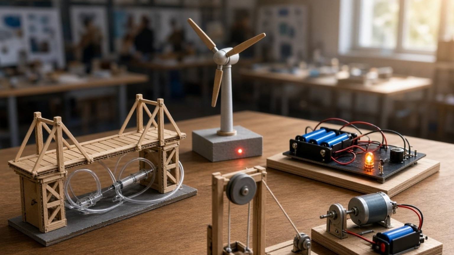
Searching for mechanical working models for a school project? This guide groups four useful diagrams: Gear and Gear Ratio, Cam and Follower, Crank and Slider, and a Water Wheel. Students in approximately Classes 7–11 can investigate rotation, speed ratios, reciprocating motion and mechanical energy transfer with simple classroom materials. Gears relate the rotational speeds of connected shafts; a cam can drive a follower along a controlled motion path; and a crank-slider links rotational and back-and-forth movement. Water flowing onto a wheel can produce rotation, but that alone is not electricity. Each poster has a full-size viewing link, project steps and short viva answers. The focus is safe observation rather than high-speed machines.
How do these four mechanisms differ?
A gear pair links shafts through interlocking teeth, allowing speed and torque relationships to change. A cam is a rotating component whose shape can influence the motion of a follower. A crank connected through a rod to a guided slider converts rotation and linear reciprocating motion. A water wheel draws mechanical energy from flowing or falling water. These are related examples of mechanisms, but they have different inputs, moving parts and outputs. Make a small comparison box beside each picture with these three labels. None creates useful energy from nothing, and all real mechanisms have some losses due to friction or other factors.
Picture 1: Gear and Gear Ratio Model
When two external gears mesh, their rotation directions are opposite. Gear tooth counts determine the ideal rotational speed ratio between connected gears. A smaller driving gear turning a larger driven gear usually produces slower output rotation with potential torque advantage in a suitable system. The reverse arrangement can increase output rotation speed but changes torque in the opposite direction. Actual behaviour includes losses and load constraints. Do not read a numerical ratio from a poster’s approximate drawn wheel size; count teeth on actual model gears. For an easy demonstration, use two cardboard wheels with safe, regularly placed teeth and rotate them slowly.

Chart note: The ratio label mixes conventions. A 12-tooth driver and 60-tooth driven gear give a driven-to-driver tooth ratio of 5:1 and an output speed one-fifth of the input. The numbered gears are not tooth counts.
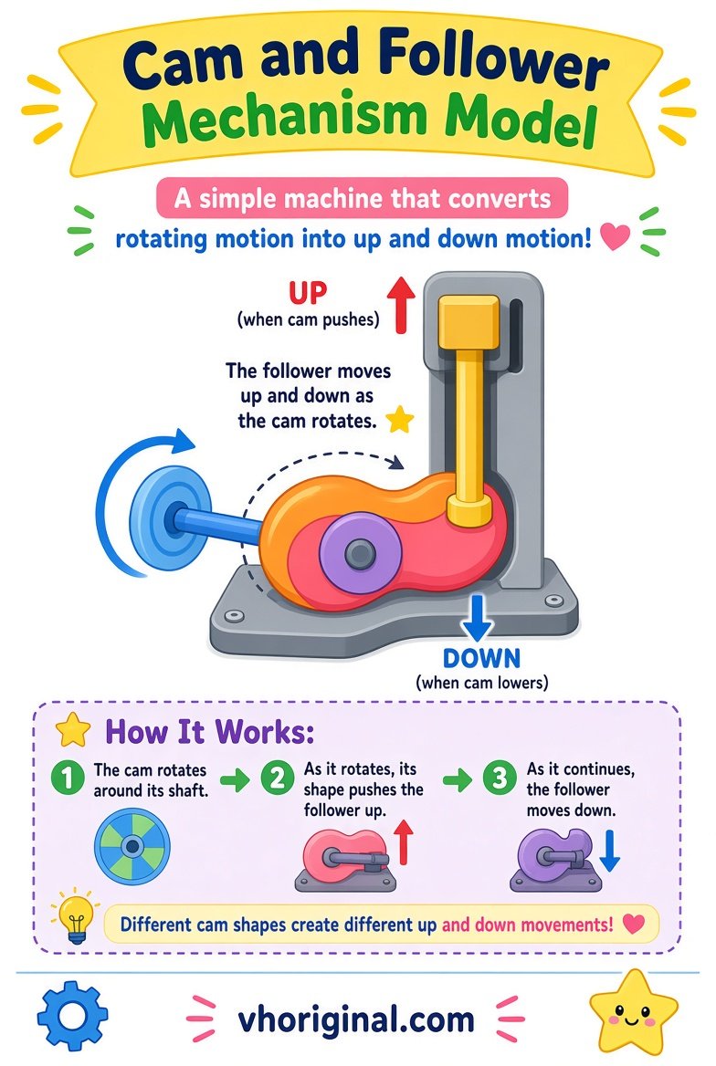
Picture 2: Cam and Follower Mechanism
A cam rotates around an axis and its contact surface shapes the follower’s movement. An eccentric circular cam provides a simple classroom example: as it turns, a follower resting on its surface may rise and fall. Some arrangements use springs while others rely on gravity to maintain contact. The profile influences the displacement, so not all cams produce the same lift or timing. Create a cardboard disc with an off-centre pivot and a light vertical follower held in a guide. Rotate slowly and observe its position. Do not dismantle powered appliances to search for a real cam; a paper model is enough.
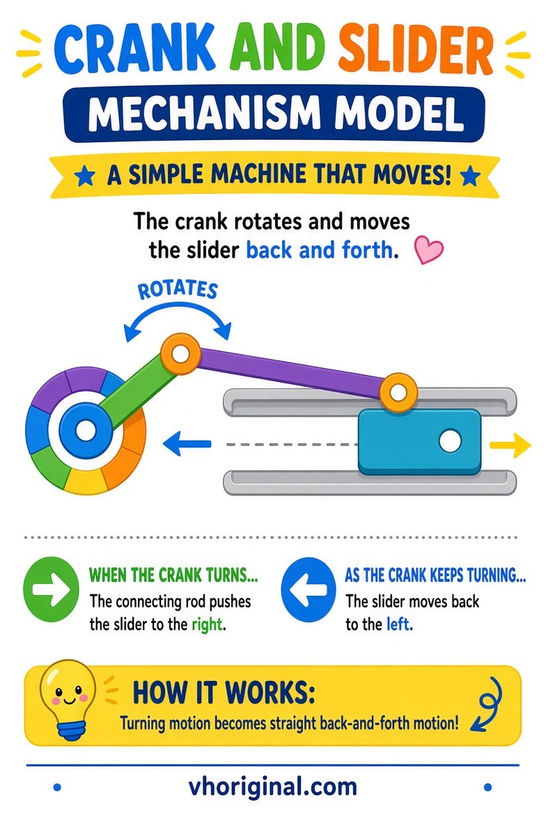
Picture 3: Crank and Slider Mechanism
A crank-slider has a rotating crank, a connecting rod and a slider constrained to move along a straight path. In suitable applications, it changes rotation into reciprocating motion or the reverse. Some engine mechanisms illustrate the principle, though real engines contain many additional parts. Build a small cardboard crank, connect it to a light paper strip and guide the slider along a straight track. Ensure that joints rotate freely without wobbling or jamming. Crank length and connecting-rod geometry affect the slider motion. A student can mark several crank positions to see where the slider moves; no electric motor is required.
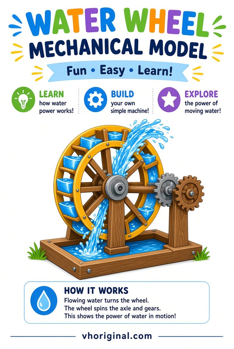
Picture 4: Water Wheel Working Model
A water wheel uses moving or falling water acting on paddles or compartments to turn a shaft. This shaft can supply mechanical rotation to a connected mechanism. Modern hydroelectric plants often use turbines with generators; a cardboard water wheel without a generator does not itself produce electricity. For a safe classroom illustration, make a lightweight wheel from card and use a small stream of clean water over a tray. Keep the setup stable, and never operate electrical devices next to spills. Label the inlet, paddles, axle, direction of water and rotation. Different wheel designs respond differently to the available flow.
Choosing a project for different class levels
Paper gears or water wheels suit younger pupils. Older students can study linkages. Choose a model appropriate to the class and explain its input, moving parts and output clearly.
Materials and step-by-step assembly
Prepare clean cardboard, paper fasteners, small safe craft sticks, rulers, pencils, markers, optional plastic gears, a light wheel and a tray. For gears, draw and cut matched teeth with adult help. For a cam, attach an eccentric disc and a guided follower. For the crank-slider, make one rotating pivot and one straight slider track. For water power, mount paddles around a light axle and pour a little clean water while protecting the desk. Test each mechanism slowly by hand. If a component jams, adjust its alignment instead of applying more power. Keep all sharp cutters under adult supervision.
Recording observations and preparing viva answers
Ask which external gear rotates faster, how a cam’s shape affects lift and whether a crank-slider changes motion direction. Record actual observations rather than made-up speed values. A teacher may ask if every spinning wheel generates electricity. Explain that a mechanical shaft requires an appropriate generator to make electricity. Another common question is whether gears increase energy: they do not. Draw small input and output arrows to help the learner explain the physical transformation. Short accurate explanations make a stronger science fair presentation than dramatic claims about efficiency or unlimited force.
Full-size downloads and safety reminders
Use full-size pictures to check arrows and pivots. Keep hands away from sharp or high-speed gears. Test cardboard parts gently; never use a power drill. For a water wheel, use a tray and separate electricity from spills.
Frequently asked questions
What determines an ideal gear ratio?
The tooth counts of the meshing gears determine their angular-speed relationship.
What does a cam and follower do?
The cam profile changes the follower’s position as the cam rotates.
What is the purpose of a crank slider?
It links rotary motion with straight-line reciprocating motion.
Does a basic water wheel make electricity?
No. It produces rotation; electrical output requires an appropriate generator.
Conclusion and sources
Mechanism projects are strongest when students can identify input, moving linkage and output while acknowledging friction and safety limitations.
Related projects: Science Working Models · Water Fountain Model
References: TeachEngineering — Simple Machines; TeachEngineering — Water Power.
Related project: levers and pulley models










Share Your Opinion
Comments are closed on this post.