 Vista
Need a simple machines school project with pictures? This guide combines three useful posters: the Six Types of Simple Machines, the Three Classes of Levers and a Pulley Working Model. Students in approximately Classes 5–9 can use them to build safe cardboard displays, label parts and answer science exhibition questions. A simple machine can change the direction, size or distance associated with an applied force, but it does not manufacture energy. The full-size diagrams make it easier to see each fulcrum, rope path and everyday example. Here you will also find safe materials, straightforward construction steps and common mistakes that can make an attractive model scientifically confusing.
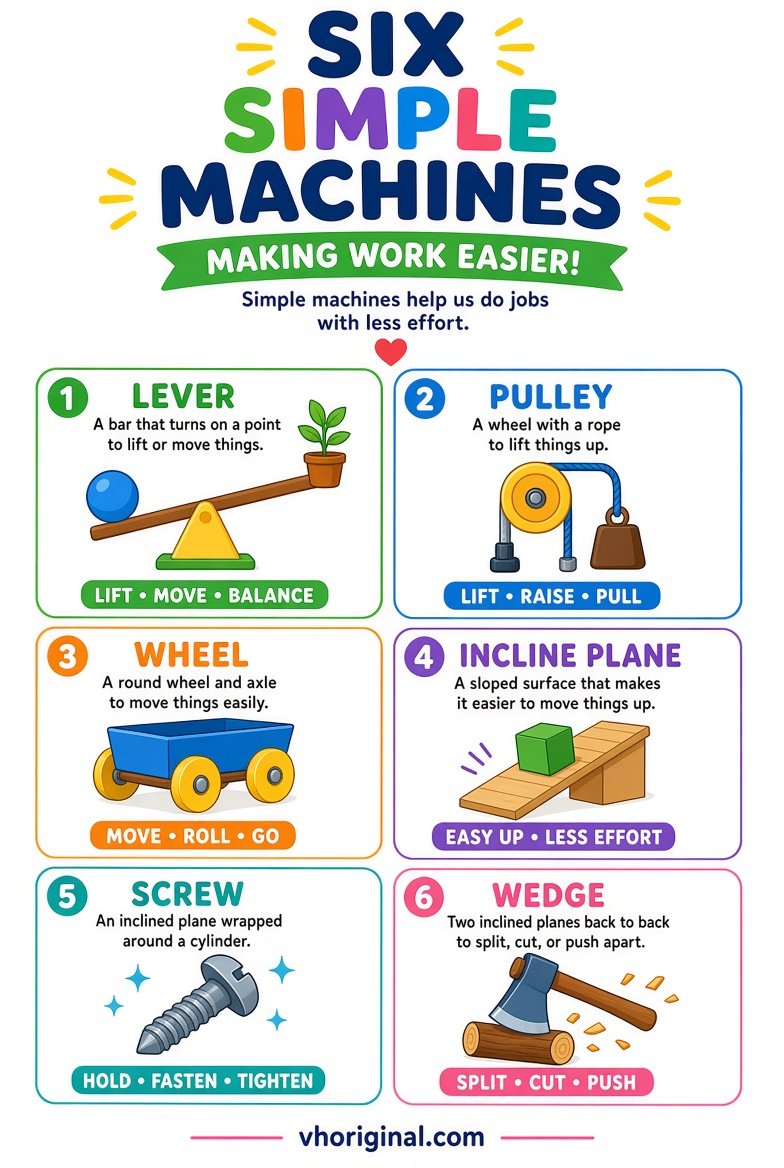
What are the six classical simple machines?
The commonly taught categories are lever, wheel and axle, pulley, inclined plane, wedge and screw. A lever acts around a pivot; a ramp is an inclined plane; a wedge can split or separate material; and a screw combines rotation with motion along its axis. A pulley guides a rope around a wheel and can change force direction or provide a mechanical advantage in suitable arrangements. A wheel and axle also changes the relation between force and motion. Real tools often combine several categories. Despite the phrase ‘makes work easier’, no machine produces useful energy from nothing, and friction causes losses.
Picture 1: Six Simple Machines Types Chart
Use the poster to connect names with familiar examples. A door handle can illustrate a wheel-and-axle system, while a loading ramp demonstrates an inclined plane. Screw threads are visible on common bolts, and some cutting tools involve wedges. Ask students to identify the feature that actually makes each device an example. One complex object may combine more than one simple machine, so a single label need not explain everything about it. A large name and one accurate example for each type is better than several unrelated pictures. Verify diagram labels before drawing them onto the final A4 page.
Picture 2: Three Classes of Levers
Lever classes depend on the relative positions of fulcrum, effort and load. In a first-class lever the fulcrum is between effort and load, as in a typical seesaw. In a second-class lever the load is between them, as in a wheelbarrow. In a third-class lever the effort lies between the fulcrum and load; a forearm acting with muscles provides a familiar teaching example. Some designs favour force advantage, while others favour speed or movement distance. Do not teach that every lever multiplies force. Label F, E and L clearly and check that the arrows point to the actual working parts.
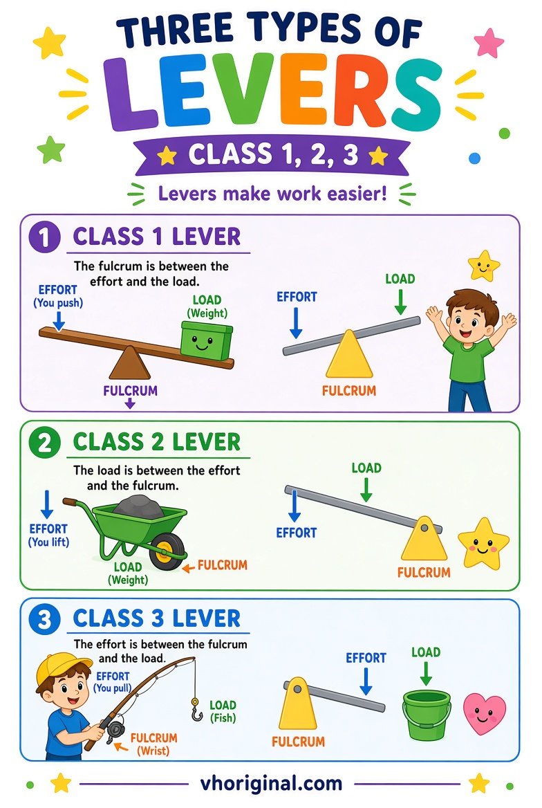
Chart note: In a second-class lever the load is between the pivot and the effort. On a wheelbarrow you lift up on the handles. For a third-class lever the effort is in the middle.
Picture 3: Pulley System Working Model
A pulley uses a grooved wheel with a rope, cable or cord. A basic fixed pulley changes the direction of pulling but offers no ideal force advantage by itself. A properly arranged moving pulley may reduce the applied force, although more rope must travel in exchange. Students can demonstrate the principle with a paper cup, string and a small wheel fixed to a sturdy cardboard support. Use only light loads and do not let a suspended object hang over anyone. Check where the rope is attached and which rope portions actually support the moving load. These details determine the behaviour.
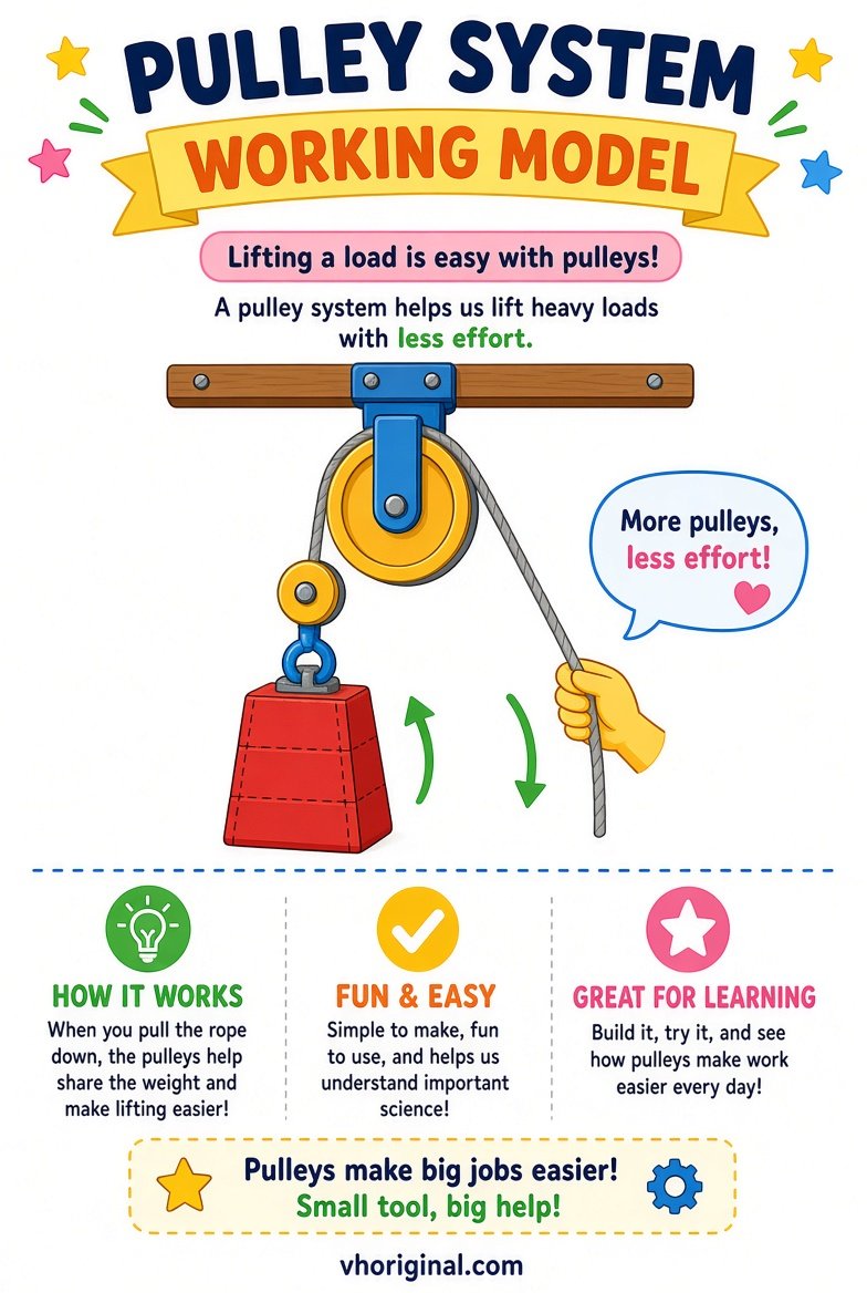
Chart note: A fixed pulley changes the direction of pull. The ideal mechanical advantage depends on how many rope segments support the moving load, not simply the number of pulley wheels.
Why mechanical advantage does not mean free energy
Mechanical advantage changes the relationship between effort, load and movement distance. Lower required force often means the effort travels farther. A fixed pulley mainly redirects force. All real machines have losses, so no mechanical setup creates free energy.
Materials for an inexpensive classroom model
Prepare clean cardboard, paper, pencil, ruler, colouring pens, tape, string, light wooden craft sticks and a small safe plastic wheel. Build the lever on a firm triangular support. Attach the pulley wheel to a well-supported frame so the string stays in its groove. Avoid sharp blades, heavy metal objects and long suspended weights in a children’s demonstration. A chart-only assignment may use printed posters as references rather than building a moving device. Keep labels large enough to read, and ask pupils to describe what the effort force actually does in each model.
Step-by-step lever and pulley construction
First choose one lever class and draw a labelled arrangement of fulcrum, effort and load. Place a light stick on the support and use a tiny paper object as the load. To illustrate another class, rearrange the positions correctly rather than simply moving the label. For a pulley, mount the wheel on a sturdy support, thread the cord through the groove and attach a light cup. Pull slowly while observing the direction of movement. For a moving-pulley variation, verify the rope attachments and supporting segments. Stop if parts jam or the support begins to tip.
Viva questions and school presentation
Ask students to name the six machine types, give one everyday example and explain what a fulcrum does. A teacher may ask if a fixed pulley halves the force; a single ideal fixed pulley does not. Another question is whether all levers magnify force; no, class and geometry matter. The best presentation shows the diagram and then demonstrates a small, controlled movement. Encourage the student to describe where energy enters the system. A machine is useful because it changes how the work is done, not because it eliminates the need to supply energy.
Full-size downloads and mistakes to avoid
Open the full-size diagrams and check fulcrum, load and effort labels. Verify each rope path and avoid claiming that a fixed pulley doubles force. Keep loads light and supports stable. Hand-drawn school assignments should use the charts as references.
Frequently asked questions
Which six simple machines are taught at school?
Lever, pulley, wheel and axle, inclined plane, wedge and screw.
What distinguishes three lever classes?
The relative arrangement of fulcrum, effort and load.
Does one fixed pulley halve the force needed?
No. An ideal single fixed pulley mainly changes pull direction.
Is a heavy load required for the model?
No. Use a small paper cup or another light classroom object.
Conclusion and sources
Students learn simple machines best when each diagram has a correct force path, real example and clearly explained trade-off between force and movement.
Related published guides: 8 Easy Science Working Models · Water Fountain Working Model
Sources: TeachEngineering — Simple Machines; TeachEngineering — Levers.
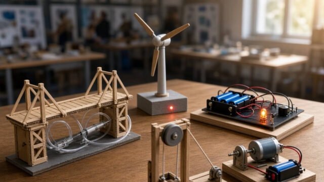
Related project: syringe hydraulic bridge model











Share Your Opinion
Comments are closed on this post.